

MetalHead was an open-source project to replace the electronics and control software in a CRS Specialties MEP MAXI 85V automatic rebar bender. I designed the controller electronics and keypad, wrote firmware, built a test fixture, and connected the controller to a Java operator interface over Ethernet.
I tested those parts separately, but the project stopped before I connected the outputs to the machine's pneumatics. It never fed, bent, or cut rebar. I had taken an engineering role at Geometrics and chose to focus my work there.
Project facts
- Machine: CRS Specialties MEP MAXI 85V automatic rebar/stirrup bender.
- My role: Custom electronics, keypad hardware, Zephyr RTOS firmware, Ethernet integration, test fixture, and Java operator interface.
- Collaborator: John Gilcreast, who provided machine access and the operator experience that shaped the requirements.
- Source: MetalHead on GitHub.
- Status: Paused prototype. Controller parts were bench-tested independently; machine operation was not tested.
Understanding the machine before replacing its controller
The original system had a controller, terminal boards, keypad, and operator display. I wanted a replacement that made it easier to see what the inputs and outputs were doing while keeping the workflow useful to someone operating the machine.
John had used the bender extensively. He helped me understand the sequence of motions, what operators needed from the controls, and what should happen when a run was interrupted.
Together, we documented a representative cycle:
- Bring the head, tooling, shear, and feed system to known home positions.
- Feed material to a calculated length while reading the encoder.
- Position the head and tooling, make the bend, and return for the next step.
- Cut the material at the required point, then continue or return home.
- After an interruption, decide whether the machine can continue or needs to return home and remake the part.
The planning notes described the feed and bend targets as:
feed target = (length + length compensation) × feed scale × bar-size modifier
bend target = (bend + bend compensation) × center-pin modifier × bar-bend modifier
These were starting points for calibration. They still needed to be checked against the machine, bar stock, tooling, and repeated measurements. We also documented cases where the head could stop between position sensors. The firmware needed a way to recover from those positions, but that behavior was never tested on the moving machine.
What I built
A 24 V interface board
The interface board connected the machine's 24 V signals to the controller. It had input circuits for encoders, proximity sensors, switches, buttons, power and fuse indications, and an emergency-stop signal.
Its MOSFET output channels were intended to control the solenoids for feeding, bending, positioning the head and tooling, and operating the shear. Each channel had an indicator LED and protection against voltage spikes.
I tested the outputs with LEDs connected on the switched side of the MOSFETs. They lit when commanded. That showed the channels could switch, but it did not test them with solenoids or prove that the machine could move safely.
A manual input test fixture
I built a fixture with two rotary encoders, proximity sensors, and buttons. Someone had to turn the encoders, trigger the sensors, and press the buttons by hand. This let me test real devices through the board's input circuits while it ran Zephyr.
The inputs worked individually on the bench. The fixture could not produce the timed, repeatable sequences I would need to test a full bending cycle or deliberately put the firmware into difficult situations.
A working keypad with too much hardware
The keypad worked on its own. An Arduino reported key presses over UART, a serial connection, and a held key began repeating after a delay.
I used two I²C GPIO expanders, an Arduino Nano/ATmega328P, conditioning circuits for each key, a discrete 16-input OR circuit, a 555 timer for the delay, and a gated oscillator for repeat pulses.
It worked, but I had used a lot of hardware for behavior that could have been handled more simply in firmware. That meant more components, connections, and things to troubleshoot.
Zephyr, Ethernet, and the operator interface
The interface board ran Zephyr RTOS. I brought up its W5500 Ethernet connection and used it to send board status to an early Java HMI, or human-machine interface.
The indicators in the HMI screenshot were live readings from the board, not a mock-up. They showed inputs, requested outputs, power status, encoder and proximity-sensor information, and firmware state.
That gave me a working path from the controller to the operator's screen. It did not show how the controller would behave while running the machine.
What I tested
| Part of the system | Test | Result and limit |
|---|---|---|
| Keypad | Pressed individual keys and held keys to check delayed repeat over UART | Worked as a separate part of the controller. |
| Inputs | Operated real encoders, proximity sensors, and buttons through the interface board running Zephyr | Inputs behaved correctly on the bench. |
| Outputs | Commanded the MOSFET channels with LEDs connected to their drain-side outputs | Channels switched; solenoids and pneumatics were not tested. |
| Ethernet and HMI | Sent live board status through the W5500 to the Java interface | Status reached the operator interface in real time. |
| Machine operation | No feed, bend, shear, or pneumatic testing took place | Not validated. |
Where the project stopped
We were close to connecting the electronics to test basic machine motions, but did not reach that point. After I moved to Geometrics, repository updates were limited to documentation, photos, and other minor work.
The controller still needed testing under actual solenoid loads, checks of motion timing, and a validated sequence for operating and recovering the machine. Its safety behavior was also untested. Continuing the project would require a machine-specific risk assessment, guarding, independent validation of interlocks and the emergency-stop system, and controlled testing on the machine.
Design review: what I would change now
Redesign the power supplies
I used large linear regulators to step 24 V down to 12 V, 5 V, and 3.3 V. They produced unnecessary heat. I also used large capacitors without controlling the initial charging current, which caused visible sparking at the power connector.
I would start a second design with switching regulators, suitable input protection, and an inrush-current-limiting MOSFET circuit for soft start. I would measure the startup behavior along with the steady operating currents and temperatures.
Simplify the keypad
I would remove the separate keypad processor and the discrete circuits for delay and repeat. An ESP32-class controller with an appropriately sized I/O expander, or a keypad matrix, could handle key debouncing and repeat timing in firmware. The choice would depend on the electrical requirements.
The original keypad worked. A simpler version would have fewer parts and make the behavior easier to test and change.
Make the input fixture programmable
A microcontroller-driven fixture could generate encoder pulses, trigger simulated proximity-switch signals, and control the timing between them. It could repeat normal cycles, interrupted runs, unexpected sensor sequences, stops between position sensors, and return-to-home tests.
That would let me exercise the same cases repeatedly before connecting the controller to the machine. With suitable electrical isolation and further development, the fixture could also help test newly assembled boards.
Use a browser interface
The Java HMI worked, but I would simplify the combination of an Orange Pi, desktop application, and separate keypad processor.
My proposed replacement would use an ESP32 to serve a Vue/Quasar web interface from a microSD card connected over SPI. A REST API would handle requests, and WebSockets would send live status to the browser. I would build the web files on a development computer; the ESP32 would serve those files, not run Node.js.
The browser interface would handle operator controls and status. It would not be responsible for safety-critical decisions. The machine's safety system and interlocks would still need separate engineering and independent validation.
What I learned
MetalHead brought together more hardware, firmware, and software than my earlier projects. The bench work showed that I could read the machine's inputs, switch output channels, use the keypad, and display live controller status over Ethernet.
It also showed me where I had made the design harder than it needed to be: hot power supplies, an overcomplicated keypad, and tests that depended on someone manually operating the fixture. Those are the first things I would change before returning to machine testing.
Visual record
Photos of the original machine electronics, custom controller and keypad, and working Java interface.
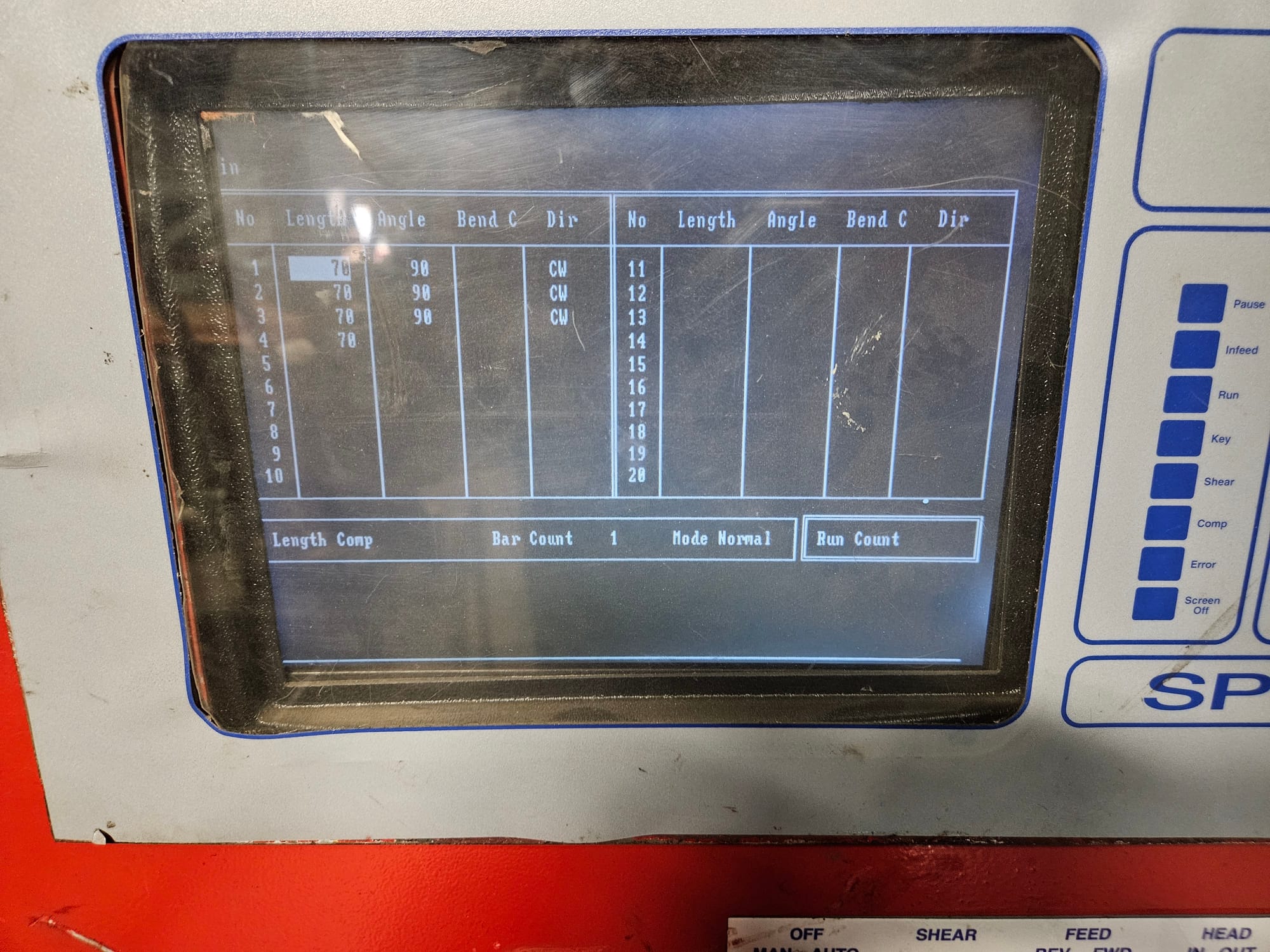
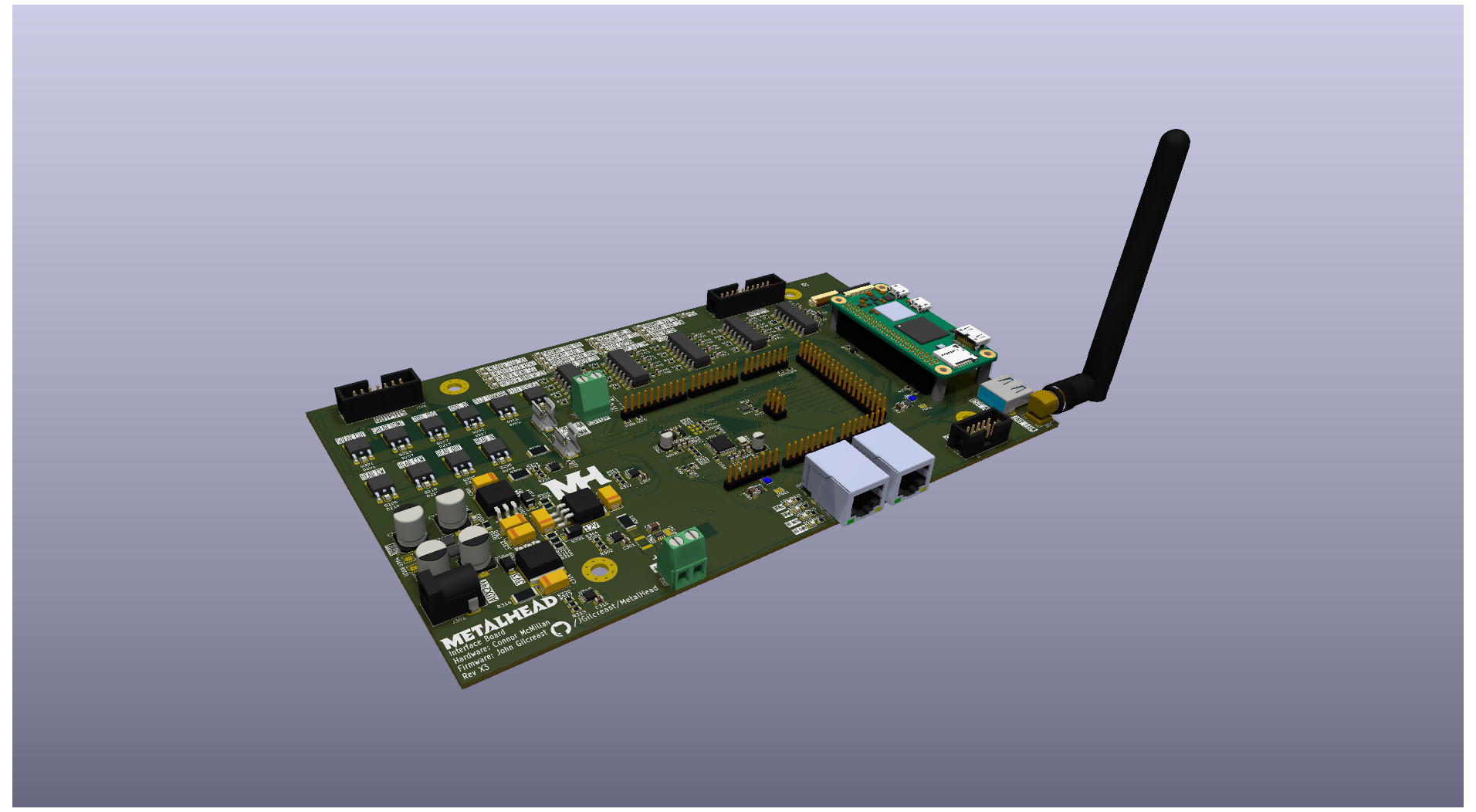
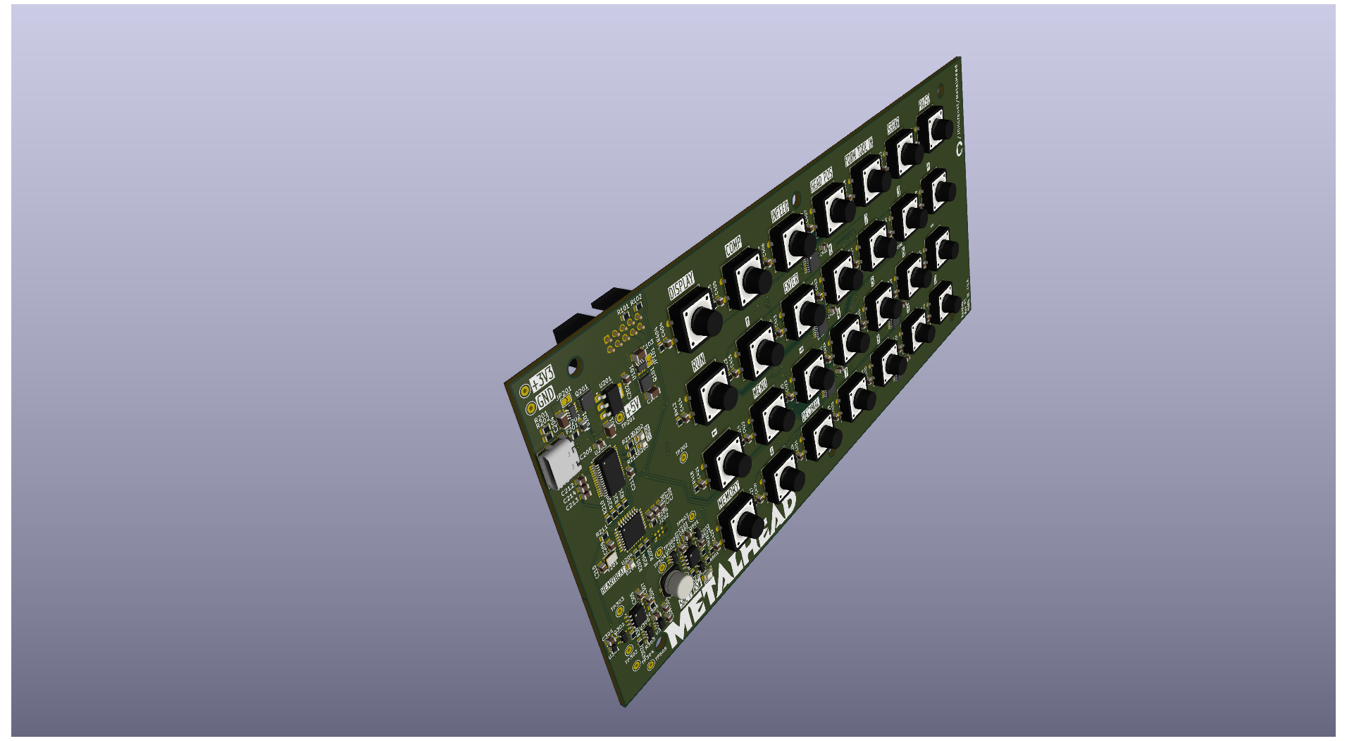
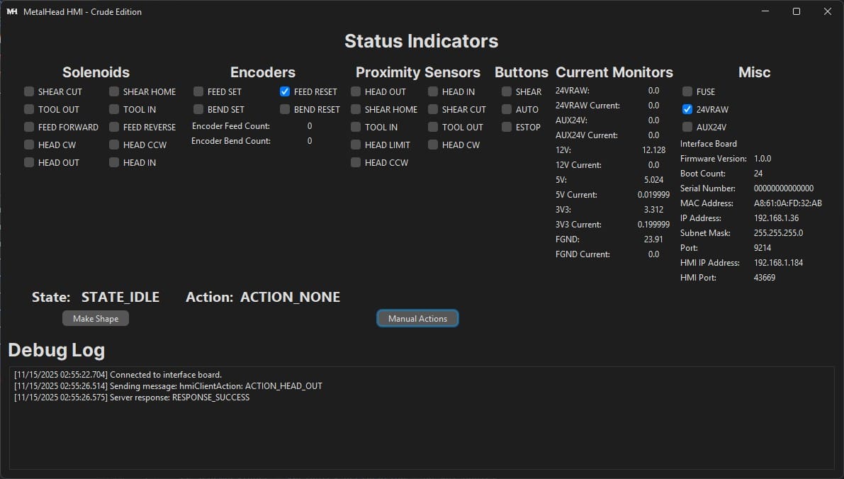
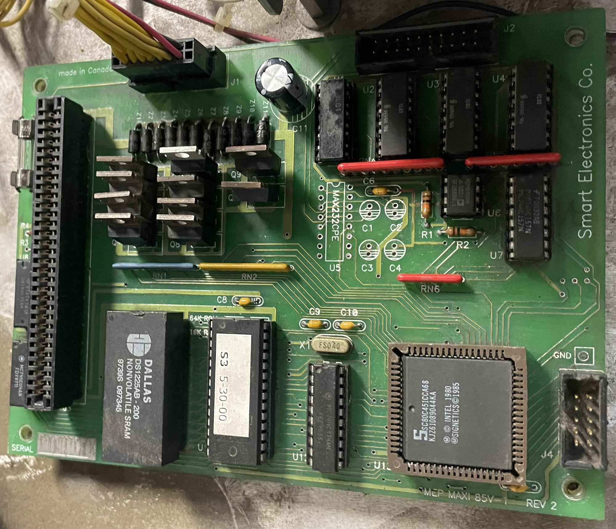
Gallery order (clockwise from upper left): the legacy machine display, the MetalHead interface-board design, the custom keypad design, the original legacy driver board, and the live Java HMI receiving telemetry from the Zephyr controller.
Revision X1 cycling through the MOSFET-gated outputs during bench testing. Unfortunately, I do not have a video of the Rev X3 test fixture.


Discussion